Many people on the forums have complained about the scales on these dishes and motors as not being accurate, which means that when they set up the dish it often takes quite a bit of trial and error to get the system aligned. Many people have commented that the elevation scale on some of the Fortec dishes is off by as much as 5 degrees. After looking up the specs for the fortec dishes, I noticed that the FC90, and most of the other Fortec dishes are advertised as having an offset angle of 24.62, while the Fortec FC80, the 80 CM dishes have an offset angle of 22.75. Since I noticed that the U-bolt dish bracket, which has the elevation scale, seems to be a generic bracket, I thought that perhaps the 5 degree errors in dish elevation might be cause by a dish bracket that was not specific to the specific dish being used. Since the pole mount brackets "seemed" to be designed for the Fortec dishes, I decided to buy the pole mount bracket with my system.
Having just received the dish and motor, before setting the system up, I decided to make some measurements, mainly to verify whether the elevation scales on the motor and dish are in fact accurate. I figured that this would also make it easier once I decided to set the dish up and start the alignment process.
SG2100 Motor measurements and comments:
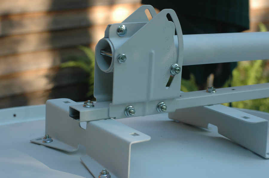
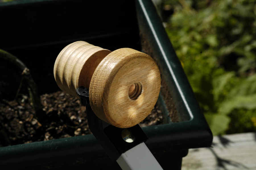
The first measurements were done on the motor. The SG2100 motor is pictured below. :
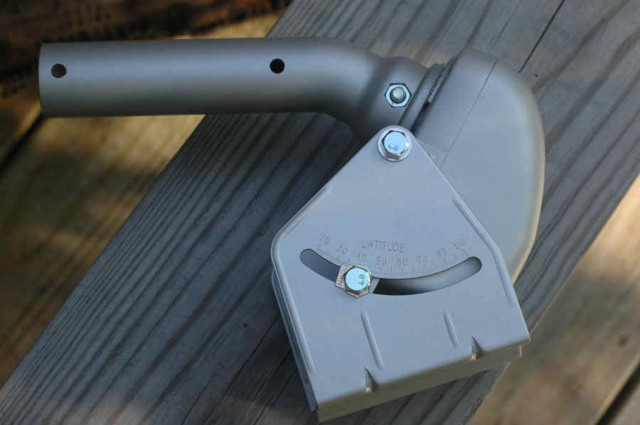
In the picture above, I've already attached the bracket, and adjusted it to a 44 deg latitude. To evaluate the accuracy of the scale, I needed to find a surface that was either parallel to the rotation axis or perpindicular to it. The picture below shows the rotation axis as the line "B", which is perpindicular to line "A", which is the crack where the 2 parts of the case are joined.

This crack could be used to measure the elevation angle, however it's more convenient to find a flat surface on the motor. As it turns out, the flat surface where the coax connectors are, is perpindicular to the rotation axis, and you can place an inclinometer on this surface to determine either the elevation angle or the latitude angle.
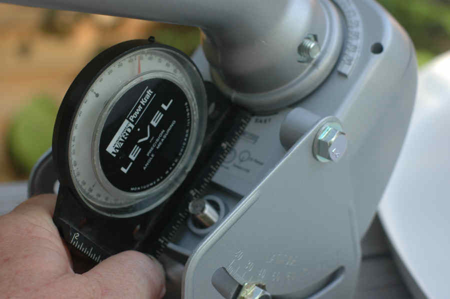
I set up the motor/bracket on a flat surface, and adjusted the angle to correspond to my lattitude, ie 44 deg, or 46 deg elevation (I'll eventually change this to 44.6 and 45.4 respectively).
Results: After adjusting the angle with the inclinometer, and tightening the bolts, the elevation angle and the latitude scale both read correctly, provided that you read the scale just above the little arrow on the washer, ie:
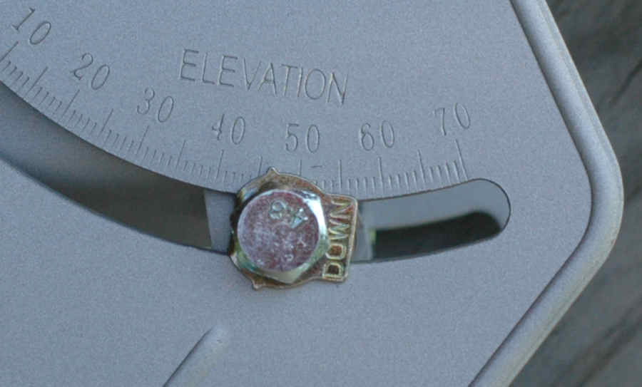
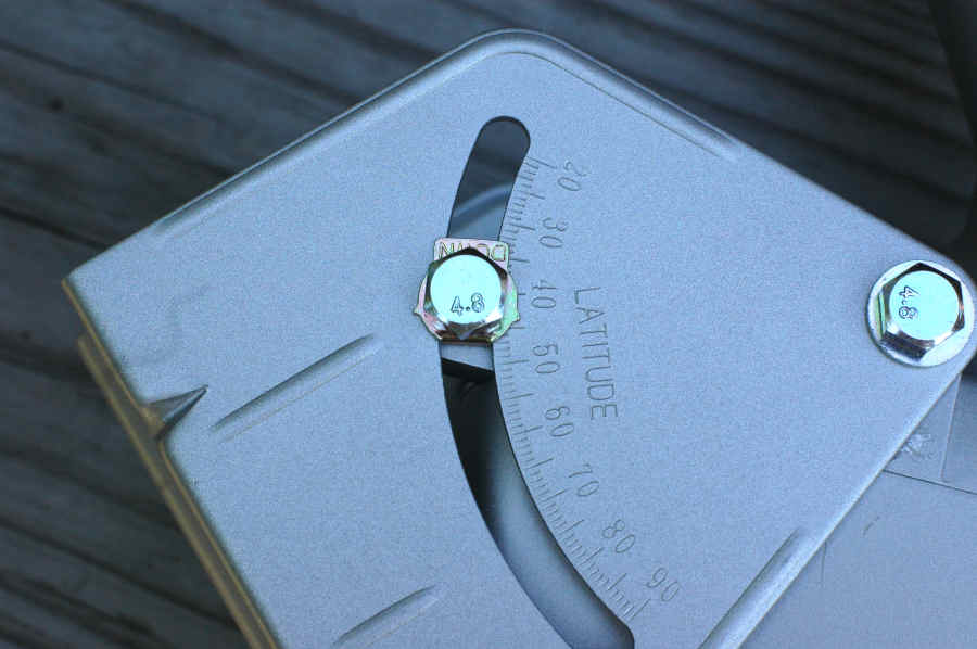
Ie I've drawn a line in the picture below showing where the most accurate indication seems to be.
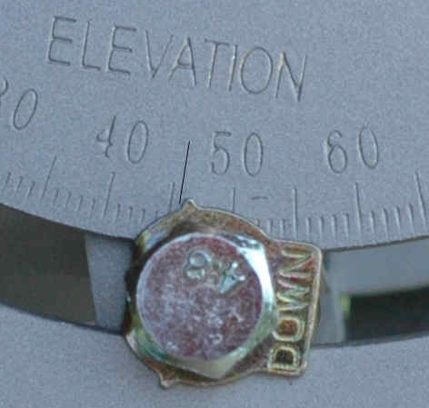
Anyway, the scale on the motor bracket seems to be fairly accurate. But I advise using an inclinometer instead of the scale.
The next measurement made on the motor, was the offset angle of the motor shaft. As seen in the first picture, the motor shaft has a bend in it, which is intended to make the dishe elevation scale usable for adjusting the declination. I used my inclinometer to measure the surface perpindicular to the rotation axis, and then measured the angle of the shaft after the bend, to determine the offset angle. The motor specification indicate that this should be 30 deg. My measurements verified this. As close as I could measure, the angle was 30 deg.
Because of this, the following equation should be used:
Dish elevation setting = 30 deg - declination .
Bottom line, is that the setup and initial adjustment of the motor angles is pretty straightforward and as accurate as is required for a 3' KU dish.
FC90P Measurements and comments.
After making measurements on the SG2100 motor, I put the FC90P together so that I could make some measurements on IT. Putting it together was not particularly straightforward, mainly because the instruction sheet did not agree at all with the actual parts received. Basically, only the dish and LNBF arm were as described on the instructions. Everything else seemed to describe an older version of the dish. In fact, the instruction sheet was labeled as that for the FC80 dish, not the FC90 dish. At first, it appeared that the brackets that attached the LNBF arm to the dish, wouldn't fit, but it turned out that if you left all the bolts loose, you could connect things even though the holes didn't appear to quite line up right. However, the fact that the parts kit, that includes the dish bracket with the elevation scale on it seem to be that for the FC80 dish, will prove to be important.
First, I layed the dish flat on it's face, and measured the angle of the LNBF bracket at the back, and then made the pole in the mounting bracket parallel to this.
I then checked to see what angle the dish elevation indicated, as this would be the angle corresponding to zero elevation, not counting the dish offset angle. As you can see in the picture below, this angle proved to be about 23.5 degrees.
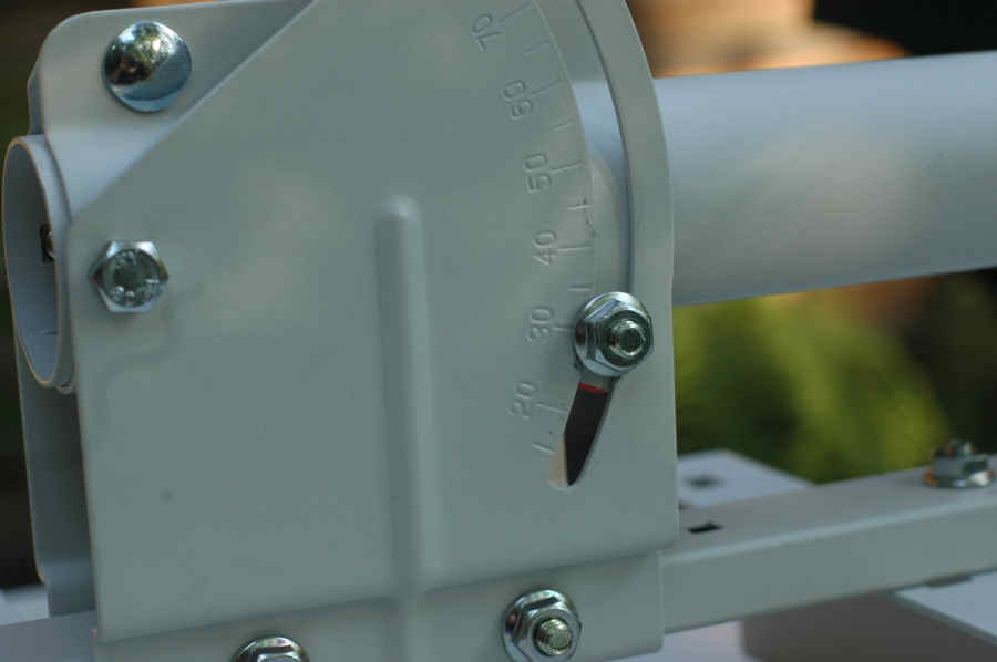
This 23.5 degree angle agrees pretty well to the specs for the FC80 dish which is supposed to have an offset angle of 22.75, but seems a bit low for the specs for the FC90 dish, which is supposed to have an offset angle of 24.62. So at this point, it seemed to be important to try to measure the actual offset angle of this dish. This is not a straightforward measurement. To do this, you have to be able to determine both the apparent aim of the dish and the actual aim of the dish. I wasn't exactly sure how to do this, but I decided that the easiest way would be to aim the dish at the sun, measure the actual angle of the sun, and measure the angle of the apparent aim of the dish. However the problem was how to aim the dish at the sun?
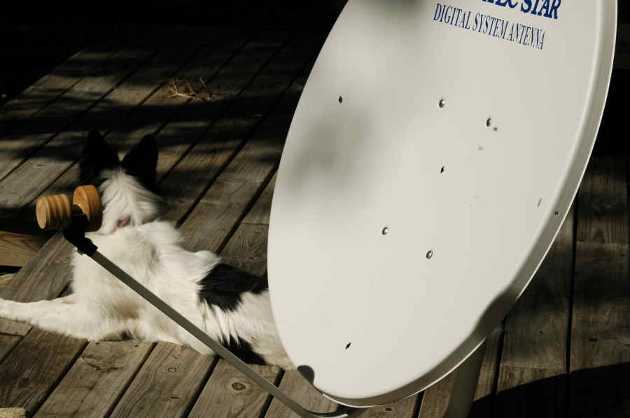
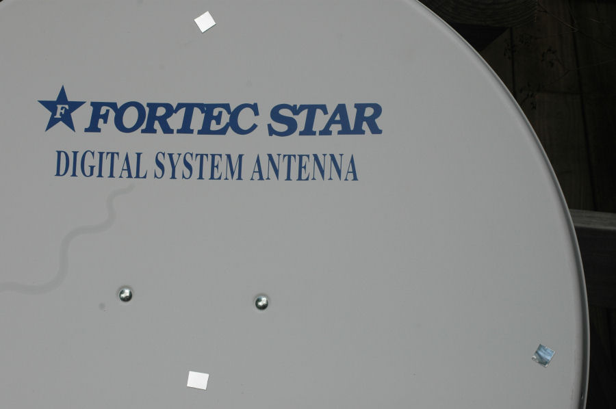
I decided to glue 5 little mirrors onto the surface of the dish, at top, bottom, right, left and center :
closeup of one of mirrors:

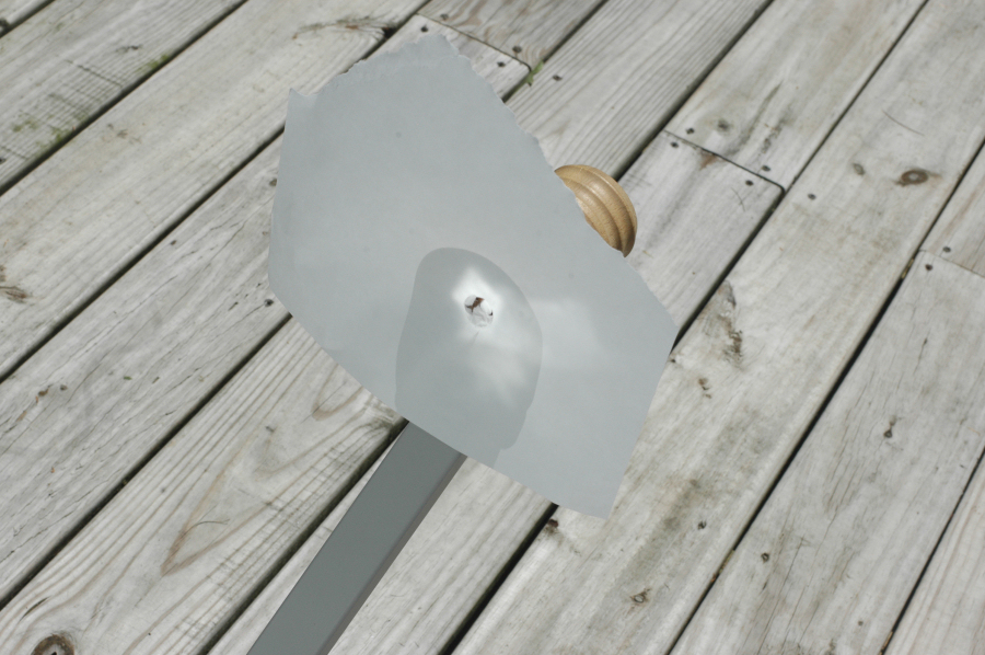
and I attached a fake LNBF into the holder,
then moved the dish until the reflections from the 5 mirrors focused on the fake LNBF, as shown above. Well part of the problem, as can be seen in the picture below, is that the 5 reflections didn't coalesce into a single spot, which is evidence that the dish surface is not perfect.
Interestingly, I actually found one spot, about an inch above the LNBF holder, where 4 of the 5 mirror spots (all except the center spot) focused at the same point, however using this focal point would require bending the LNBF arm, which I didn't want to do at this point. But it does look like the dish seems to be shaped fairly well if another focal point would be used. Perhaps an experiment for the future.
Anyway, I aimed the dish at the sun, and while the spots were all hitting the fake LNBF, I measured the angle at the center of the dish, and at the dish arm, and also measured the elevation of the sun, using a yard stick adjusted to have it's shadow as small as possible. Using this method, I determined the offset angle of the dish to be approximately 25 degrees, which is fairly close to the 24.62 specification. It is not as close to the 23.5 degree setting determined for the dish bracket, however, as this dish bracket was probably made for the FC80 dish with the 22.75 offset angle.
The result of this discrepancy is that the requirred dish elevation will be less than would be predicted if the dish bracket scale were accurate.
###############################################################
Update #1:
Being concerned about the fact that the 5 little mirrors don't all reflect to the same focal point, but not being sure if the thickness of the mirrors was altering the results, I decided to try to find a THIN mirror material, that wouldn't be substantially different from the surface of the dish.
I first tried gluing on small squares of aluminum foil. I thought this would work, however it wasn't a perfect enough reflector, and I wasn't able to see the spots on my fake lnbf.
Since I live in an area with natural mica, and having noticed how mica rocks will reflect the sun very well for hundreds of feet, I thought that might be a good surface, plus mica sheets can be separated to individual sheets that are much thinner than a sheet of paper, probably thinner than the paint on the dish. However, this didn't work either. I'm not exactly sure why. Perhaps when I separated the layers with a knife, I fractured the surface enough to ruin the optical properties.
Then I went to the hardware store, and got 2 things. First, I got some very reflective aluminized tape, which "seemed" to have good optical properties. However, again, this didn't work. Again, don't know why.
Finally, at the hardware store, in the automotive section, I found a sheet of mirror repair material. It is similar to thick aluminum foil, but of fairly good optical quality. You can cut it with sissors. I cut 5 little squares of this material, and glued them to the dish, as shown:
Anyway, this worked well. However, while slightly better than when using the thicker mirrors, it still showed that the different squares didn't reflect to the same points:
This seems to show 2 of the 5 squares reflecting at one point, but the other 3 being off center.
At this point, I again tried to find another focal point at which all 5 reflectors aimed at the same point.
What I found, was that above, and a bit to the left of the regular focal point, there was a much better focal point, where all 5 reflections came nearly together:
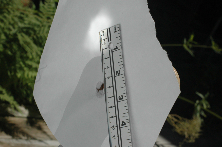
As you can see above, this was about 2.5" off center, and the surface of the paper was about 1" forward of the plane defined by the lnbf holder.
At this point, I was tempted to try to bend the LNBF arm, and/or place some washers on the upper dish bracket, between it and the dish , to bring the lnbf holder up to where the real focal point is. However, before doing anything this drastic, I decided that I want to make an LNBF adapter that fits into the regular lnbf holder, but places the lnbf at the altered position. If I can figure this out, I'm going to set the dish up, and compare signal strengths with the regular lnbf position and with the lnbf adapter, to see how much this helps. If it helps a lot, I'll consider bending the lnbf arm.
HOWEVER....... I really recommend anyone who is considering putting up one of those multi-lnbf dishes to do the above mirror experiment. Because it will demonstrate that an off center lnbf will NOT perform nearly as well as the lnbf that is centered at the focal point. Basically, a parabolic sat dish will have only one focal point.
##################
More to come.